About Metal Seals
Seal Dynamics
The sealing performance of any elastic metal seal is based on the relative high specific contact load between the seal and the mating surface. This linear load or seating load is generated by the reaction of the seal (with or without spring) against its deformation by compressing the seal to a well-defi ned groove depth.
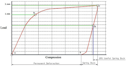
The graph on this page represents the compression and decompression characteristics of a standard spring energised C Ring. The curve “A-B-C” gives the increasing linear load by compression rate, whereas the curve “C-D-E” represents the reduction of linear load when the seal flanges separate and compression is reduced.
The curve shows a plastic deformation of the metal seal. Point “B” on the compression curve is the transition point between elastic and plastic deformation. In this example almost 80% of the max. linear load is achieved. Point “C” indicates the point of maximum compression (min. groove depth). Metal seals should be compressed approximately 20%, as higher compression can lead to seal failure.
The total spring back or elastic recovery is situated from point “C” to “E”. As a rule of thumb, the spring back varies between 4 and 6% of the original cross section of the seal. It will be clear that as soon as the flange separation equals the spring back, the seating load will fall back to zero. At that point the sealing performance will be highly questionable. Therefore it is strongly advised to design flange and bolts in such a manner that the flange rotation at the seal location is smaller than 1/3 of the total spring back. The latter is outlined with the green coloured section of the decompression curve.
For safe operation the seal has to be maintained in the green section (line C-D) of the decompression curve. Depending on the number of variables it might be required to move point “D” upwards, i.e. reducing the useful spring back.


